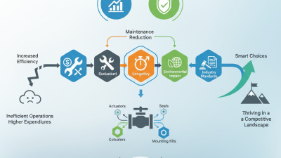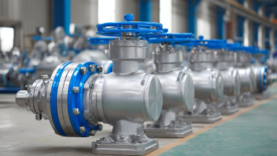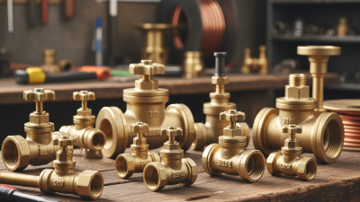
Choosing the right valves accessories is not a minor purchasing decision. It affects sealing, control, maintenance, safety, and operating costs across an entire system. A poorly matched actuator, gasket, positioner, or limit switch can turn a reliable valve into a recurring failure point.
Market evidence shows why this decision deserves engineering attention. Grand View Research’s Industrial Valves Market Size, Share & Trends Analysis Report, 2024–2030, estimates continued global market growth through 2030. Its analysis highlights demand from water treatment, oil and gas, chemicals, power generation, and manufacturing. However, market growth does not guarantee correct selection. Conditions still matter. Pressure, temperature, fluid composition, cycling frequency, connection standards, and available maintenance skills should guide every specification.
As valve-industry educator Greg Johnson has explained, “The valve is the final control element in a process control loop.” That principle also applies to valves accessories. An accessory should support the valve’s actual duty, not merely fit its dimensions. Check torque requirements, fail-safe action, corrosion resistance, enclosure rating, response time, and spare-part availability. A stainless-steel positioner may suit a wet chemical plant, while a simpler unit may perform better in a clean indoor utility room.
Reports can provide useful direction, but they cannot replace site experience. Product catalogs may also hide practical limitations. I have seen selections fail because engineers overlooked sunlight, vibration, or inconsistent instrument air. That is an uncomfortable reminder. The cheapest package is rarely the lowest-cost solution. Choose valves accessories with documented compatibility, verified certifications, and a maintenance plan that technicians can realistically follow.
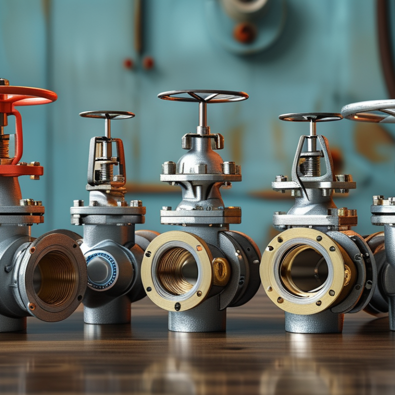
Valve accessories improve control, safety, feedback, and maintenance. An actuator converts air, electricity, or hydraulic power into valve movement. A positioner adjusts movement according to the control signal. It helps the valve reach the required opening more accurately. Solenoid valves control air supply to pneumatic actuators. Limit switches confirm whether the valve is open or closed. These small devices often prevent larger operating problems.
Tips: Match every accessory with the valve size, medium, pressure, temperature, and control system. Check the actuator’s torque, not only the valve diameter. Use a filter regulator for clean, stable instrument air. Confirm enclosure protection when moisture, dust, or outdoor exposure is expected. Keep wiring and tubing clearly labeled.
A practical selection begins with the process conditions. Corrosive fluids may require suitable materials and protective enclosures. Fast cycling may need a stronger actuator and better cushioning. Manual overrides can help during controlled maintenance, but they need clear operating instructions. In field checks, loose tubing and incorrect switch settings are common findings. I have also learned that “compatible” does not always mean reliable. A positioner may fit mechanically but fail with an unsuitable signal. Review drawings, connection sizes, fail position, and maintenance access before ordering. Leave room for inspection. Small oversights become expensive delays.
How to Choose the Right Valves Accessories?
Identifying the valve type comes before selecting accessories. A butterfly valve suits many quarter-turn applications, while a globe valve offers more controlled throttling. Check the medium, temperature, pressure, and flow direction. Water, steam, corrosive chemicals, and abrasive slurries demand different body and seal materials. In field inspections, I have seen a suitable actuator fail because the valve required a higher breakaway torque than expected. That small detail matters.
Size the valve from flow data, not pipe diameter alone. A 100-millimeter pipe may still need a smaller control valve, depending on velocity and pressure loss. Review the valve coefficient, often listed as Cv or Kv, then compare it with the operating range. Oversizing can cause unstable control and rapid seat wear. Undersizing creates excessive pressure loss. The U.S. Department of Energy reports that compressed-air leaks may waste 20–30% of compressor output, so accessory selection should also include reliable position feedback and leak-resistant connections (Improving Compressed Air System Performance, 2020).
Operating requirements shape the final accessory list. Specify actuator torque, fail-safe position, cycle frequency, enclosure rating, signal type, and ambient temperature. For outdoor equipment, moisture ingress and condensation deserve practical attention. International standards such as ISO 5211 help align actuator and valve mounting dimensions, but field tolerances can still surprise you. Do not trust a catalog number blindly. Recheck actual pressure, temperature, and shutdown conditions before ordering. Sometimes the first specification is simply wrong.
| Valve Type | Typical Applications | Common Nominal Sizes | Typical Pressure Class or Rating | Typical Operating Temperature | Recommended Operating Method | Common Accessories | Key Selection Requirements |
|---|---|---|---|---|---|---|---|
| Ball Valve | On/off isolation for water, air, gas, oil, and many compatible process fluids | DN15–DN300 ½–12 in |
Class 150–600; some designs are rated by PN16–PN100 | Approximately −29°C to 200°C, depending on body, seat, and packing materials | Manual lever for small sizes; electric or pneumatic actuator for automated service | Electric actuator, pneumatic actuator, solenoid valve, limit switch box, position indicator, lockout device, mounting bracket | Confirm full-port or reduced-port design, media compatibility, seat material, required shutoff level, torque, and fire-safe requirements where applicable |
| Butterfly Valve | Large-diameter isolation and flow regulation in water, HVAC, cooling, and low-pressure process systems | DN50–DN2000 2–80 in |
Commonly PN6–PN25 or Class 150, depending on design | Approximately −20°C to 200°C; resilient-lined versions generally have lower temperature limits | Manual handle or gearbox; electric and pneumatic actuation for frequent or remote operation | Gearbox, electric actuator, pneumatic actuator, solenoid valve, limit switch box, positioner, extension stem | Check wafer, lug, or flanged installation; verify disc clearance, face-to-face dimension, pressure drop, lining material, and required operating torque |
| Gate Valve | Full-flow isolation in pipelines where the valve is normally fully open or fully closed | DN50–DN1200 2–48 in |
Class 150–600; PN10–PN100 designs are also common | Approximately −29°C to 400°C, depending on trim, packing, and body materials | Handwheel and rising or non-rising stem; electric actuator for large or remote valves | Electric actuator, gearbox, limit switches, position indicator, stem extension, locking device, bypass arrangement | Not normally recommended for throttling; confirm wedge or parallel-gate design, stem direction, installation clearance, and actuator thrust or torque |
| Globe Valve | Flow regulation, throttling, and isolation in steam, water, thermal-fluid, and process systems | DN15–DN400 ½–16 in |
Class 150–600; PN16–PN100 designs are available | Approximately −29°C to 450°C, subject to body and trim materials | Manual handwheel for local control; pneumatic or electric actuator for modulating service | Pneumatic actuator, electric actuator, valve positioner, I/P converter, air filter regulator, limit switches, handwheel override | Evaluate flow coefficient, allowable pressure drop, cavitation risk, actuator thrust, trim material, control accuracy, and fail position |
| Check Valve | Prevention of reverse flow in pumps, compressors, pipelines, and water systems | DN15–DN1200 ½–48 in |
Class 150–600; PN10–PN100 designs are common | Approximately −29°C to 400°C, depending on the body and sealing materials | Self-actuated by fluid flow; some axial or swing designs include dampers or hydraulic controls | Hydraulic dashpot, counterweight, position indicator, limit switch, external bypass, flow restrictor | Confirm flow direction, minimum flow velocity, cracking pressure, allowable reverse pressure, water-hammer risk, installation orientation, and closure speed |
| Plug Valve | On/off isolation for gas, oil, slurry, and process fluids requiring a compact quarter-turn valve | DN25–DN600 1–24 in |
Class 150–600; some designs are rated PN16–PN100 | Approximately −29°C to 260°C, depending on lining, seals, and lubrication system | Manual lever or gearbox; pneumatic or electric actuator for automated operation | Electric actuator, pneumatic actuator, solenoid valve, limit switch box, position indicator, sealant injection system | Check lubricated or non-lubricated construction, plug torque, sealing system, media solids, emissions requirements, and actuator sizing |
| Diaphragm Valve | Corrosive, abrasive, hygienic, or contaminated fluids where the process fluid should be isolated from the operating mechanism | DN15–DN300 ½–12 in |
Commonly PN6–PN16 or lower-pressure service | Approximately −10°C to 150°C, depending on diaphragm and lining material | Manual handwheel; pneumatic actuator for automated control or frequent cycling | Pneumatic actuator, electric actuator, solenoid valve, positioner, limit switches, air filter regulator | Verify diaphragm material, lining compatibility, vacuum capability, pressure-temperature limits, flow direction, and cycle frequency |
| Safety Relief Valve | Protection of pressure vessels, boilers, pipelines, and process equipment against excessive pressure | Inlet sizes commonly DN15–DN300 ½–12 in |
Set pressure must be selected below the equipment allowable working pressure and verified against the applicable code | Approximately −29°C to 400°C, depending on spring, body, nozzle, and service | Spring-loaded or pilot-operated; normally self-actuated by system pressure | Test gag, lifting lever, rupture-disc combination, discharge silencer, weather hood, position switch | Specify set pressure, relieving capacity, back pressure, fluid phase, temperature, discharge arrangement, code requirements, and certification needs |
| Control Valve | Automatic regulation of flow, pressure, temperature, or liquid level in process systems | Commonly DN25–DN600 1–24 in |
Often Class 150–600; pressure rating depends on body and trim design | Approximately −29°C to 400°C, depending on materials and packing | Pneumatic diaphragm or piston actuator; electric actuator where instrument air is unavailable | Valve positioner, I/P converter, air filter regulator, solenoid valve, booster relay, volume tank, travel transmitter, limit switches | Calculate required flow coefficient, rangeability, noise, cavitation, flashing, actuator fail action, signal type, and available instrument-air pressure |
| Pinch Valve | Abrasive slurries, powders, granules, and fluids containing suspended solids | DN25–DN1200 1–48 in |
Commonly low to medium pressure, often up to approximately PN16 | Approximately −20°C to 120°C, depending on sleeve material | Manual, pneumatic, or hydraulic operation | Pneumatic actuator, solenoid valve, air filter regulator, limit switches, position indicator, pressure regulator | Prioritize sleeve compatibility, abrasion resistance, minimum and maximum pressure, vacuum capability, closing force, and maintenance access |
| Knife Gate Valve | Slurry, pulp, wastewater, bulk solids, and other services containing suspended particles | DN50–DN1600 2–64 in |
Commonly PN6–PN16; some heavy-duty designs use higher ratings | Approximately −20°C to 200°C, depending on seat, packing, and body materials | Handwheel or gearbox; pneumatic or electric actuator for remote operation | Pneumatic actuator, electric actuator, solenoid valve, limit switch box, position indicator, stem extension | Confirm unidirectional or bidirectional sealing, slurry concentration, gate clearance, seat design, actuator thrust, and leakage requirements |
How to Choose the Right Valves Accessories?
Matching Accessories with Pressure, Temperature, and Media Conditions
Valve accessories should match the system’s real operating conditions, not only the valve size. Start with pressure ratings, including startup surges and pressure fluctuations. An actuator may work during testing but fail under repeated high loads. Check its torque margin carefully.
Temperature changes affect seals, tubing, positioners, and electrical enclosures. Low temperatures can make elastomers brittle. High temperatures may damage wiring or reduce lubrication performance. Select materials with documented temperature ranges, then verify those limits under continuous operation. Small details matter.
The process media also requires close attention. Moisture, chemicals, abrasive particles, and oxygen-rich service can affect material selection. Use compatible seals, corrosion-resistant tubing, and suitable fittings. For dirty media, a filter may protect the positioner and solenoid valve. A protective enclosure can help in dusty areas.
One common mistake is trusting the normal pressure shown on a process sheet. Actual conditions may change during cleaning, shutdown, or emergency operation. Review those scenarios with maintenance and process engineers. Confirm connection standards, fail positions, response times, and inspection access. Keep records of certificates and test results. Recheck assumptions. It is worth the extra hour.
Compatibility must cover the full assembly, including actuators, positioners, gaskets, tubing, and electrical connections. Check thread standards, torque requirements, signal types, enclosure ratings, and response times. Safety depends on more than a valve’s pressure rating. IEC 61508 supports a risk-based approach to functional safety, while ISO 13849 helps evaluate safety-related control systems. Certification should match the application, not merely decorate a datasheet. Relevant documentation may include pressure testing, material traceability, ingress protection, and hazardous-area approvals. Requirements vary by location and service.
Choosing valve accessories starts with the service, not the catalog. Define pressure, temperature, fluid chemistry, flow direction, and failure position. Then match the valve, actuator, positioner, solenoid, limit switches, gauges, and connectors as one assembly. In field commissioning, a mismatched actuator often causes slow travel, hunting, or incomplete shutoff. An actuator needs torque margin, but excessive margin can damage seats. Use sizing calculations, then verify them against operating data. I have seen perfect specifications fail because the actual process was different.
Installation is where small errors become recurring costs. Keep piping aligned, support heavy accessories, and protect instrument-air lines from moisture. Calibrate the positioner after mounting, not only on the workbench. Check fail-safe action during a controlled test. The U.S. Department of Energy’s Improving Compressed Air System Performance sourcebook reports that leaks can waste 20–30% of compressor output. For pneumatic valves, tubing, fittings, and solenoids belong in the energy audit. The IEA’s Energy Efficiency 2023 report places industry near 37% of global final energy use. Small assembly losses matter. Record stroke time, air pressure, leakage, cycle count, and packing condition. Reports guide decisions, but plant evidence wins.
Tips: