How to Choose a Three Way Ball Valve?
Choosing the right three way ball valve starts with understanding the system, not browsing product photos. In real installations, a valve may control water, compressed air, oil, or a mildly corrosive process fluid. Each medium changes the material, seal, and pressure requirements. A stainless steel body may suit demanding environments, while brass can work well in many general service applications. The correct choice depends on verified conditions.
Port configuration matters. A T-port valve can mix or divert flow, while an L-port design usually switches flow between two connected paths. However, manufacturers may describe these patterns differently. Always check the flow diagram. A small drawing can prevent a costly installation mistake. It is also important to confirm pipe size, connection type, operating temperature, and maximum working pressure. Do not rely only on nominal size.
Manual operation may be enough for occasional adjustment. Automated systems often require an electric or pneumatic actuator, along with feedback and suitable control signals. Consider access space, maintenance needs, cycle frequency, and the consequences of failure. A normally open or normally closed position may affect safety and process stability. It should never be guessed.
A reliable selection process uses technical datasheets, recognized standards, and advice from qualified suppliers. Product claims still need verification. A neat specification sheet can hide practical limitations. Field experience also matters, because alignment, contamination, and poor sealing can shorten service life. There is no universal best valve. The most suitable three way ball valve is the one that matches the fluid, flow path, operating conditions, and long-term maintenance plan. Mistakes happen. Careful checking reduces them.
Define T-Port or L-Port Flow Needs for 2-, 3-, or 4-Way Routing
How to Choose a Three Way Ball Valve?
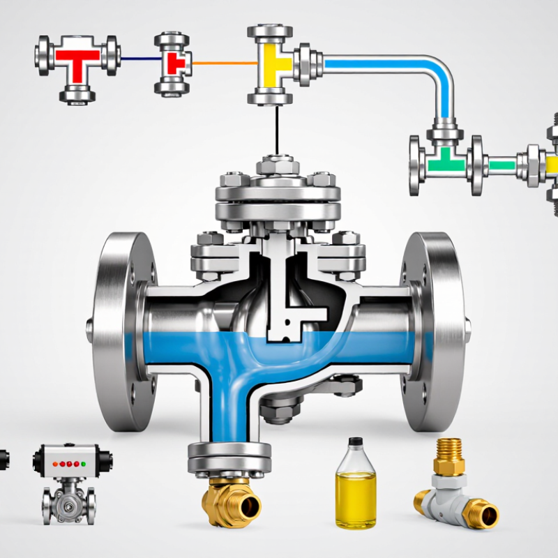
Start by defining the required routing pattern, not the valve size. A three-way valve has three ports, but your system may need two, three, or four distinct flow routes. An L-port ball valve normally directs flow from one common port to either of two outlets. It suits simple switching, such as selecting Tank A or Tank B. The flow path is clear. The valve cannot usually connect all three ports at once.
A T-port design offers more combinations. Depending on the handle position, it can connect two ports or link all three. This makes it useful for mixing, diverting, and temporary bypass service. For four-way routing, check the actual position diagram carefully. A single three-way valve may provide four usable routing states, but it still has only three physical ports. Some systems need indexed stops, a manifold, or two valves. Do not assume “T-port” automatically means every route is available. I have seen layouts fail because the handle pattern was never tested under pressure.
Tips: Draw each desired route with arrows. Mark the inlet, outlet, and blocked port. Then compare the sketch with the manufacturer’s port-position chart. Confirm whether simultaneous flow is acceptable, and check the actuator’s turning range. A small mismatch can send fluid toward the wrong branch. Wet testing is better than relying on memory.
How to Choose a Three-Way Ball Valve?
Define the required flow routing first. An L-port three-way ball valve connects two ports at a time, while a T-port design can connect two or three ports depending on the handle position. Four-way routing requires a four-port valve arrangement rather than a standard three-way valve.
Use an L-port configuration for simple diverting or selecting between two outlets. Choose a T-port configuration when mixing, diverting, or selecting among three connected flow paths is required. If the system must route flow through four ports, specify a four-way valve or a multi-valve assembly.
Select Body and Seat Materials for Temperatures up to 500°C
Choosing a three-way ball valve for 500°C service starts with heat, not port geometry.
500°C equals 932°F, where ordinary soft seats can deform, carbonize, or lose preload. PTFE is usually unsuitable, while PEEK may fit moderate high-temperature duties after pressure and cycle checks. For near-500°C service, graphite-filled or metal seats are more realistic. Seat limits vary by grade and design. Do not trust a generic catalog line.
The body must match pressure, oxidation, and thermal-cycling demands.
Carbon steel can work in controlled atmospheres, but stainless or heat-resistant alloy steel offers better oxidation resistance. ASME B16.34 requires pressure-temperature rating evaluation. A 500°C label does not preserve the valve’s full pressure rating. Check shell strength, stem material, packing, bolting, and thermal expansion together. A three-way cavity can trap heat and distort alignment. Small clearances matter.
The U.S. Department of Energy’s Improving Steam System Performance sourcebook
identifies leakage and poor insulation as recurring energy losses. Field assessments commonly report losses approaching 20% in poorly maintained systems. That figure is not a valve rating, but it shows why sealing deserves attention. Specify high-temperature leakage testing, cycling tests, and fire-safe performance under API 607 where relevant. I would also question whether 500°C is continuous or intermittent. A valve surviving a brief spike may fail after repeated cycles. Ask for tested pressure-temperature curves, seat leakage results, and packing limits.
Size the Bore Using Cv, Flow Rate, Pressure Drop, and Media Viscosity
How to Choose a Three Way Ball Valve?
Size the Bore Using Cv, Flow Rate, Pressure Drop, and Media Viscosity
Selecting the bore starts with actual flow conditions, not pipe size alone. Record the required flow rate, available pressure drop, fluid temperature, and specific gravity. For liquids, a basic estimate uses Cv = Q × √(SG ÷ ΔP). Q represents flow, while ΔP is the pressure loss across the valve. Use consistent units. A wrong unit can produce a dangerously confident answer.
Media viscosity needs attention. Thick oil, syrup, or polymer solutions may require a viscosity correction to the calculated Cv. Higher viscosity usually increases resistance and reduces capacity. Check the valve’s published flow data at the operating temperature. A large bore may reduce pressure loss, but it can also make low-flow control unstable. The three-way port pattern matters too. L-port and T-port arrangements create different flow paths and mixing behavior.
Tips: Calculate the smallest practical bore first. Then compare it with the pipeline diameter and the valve’s rated capacity. Ask for test data when the fluid is unusually viscous. Do not size from water data alone. Recheck the result at minimum and maximum flow, because one operating point rarely tells the whole story. The calculation is only an estimate. Real installations include fittings, turbulence, and changing fluid properties. I would also leave a controlled margin, but not an excessive one. Oversizing is easy to justify and harder to correct.
How to Choose a Three Way Ball Valve? - Size the Bore Using Cv, Flow Rate, Pressure Drop, and Media Viscosity
The following table provides a practical liquid-service screening method for selecting a three-way ball valve bore. The calculated Cv is based on the required flow and pressure drop; the final valve must be checked against the actual port geometry, flow path, temperature, viscosity correction method, shutoff pressure, and manufacturer flow coefficient data.
Illustrative Three-Way Ball Valve Bore-Sizing Cases for Liquid Media
| Case |
Media and Operating Temperature |
Flow Rate
Q (US gpm) |
Specific Gravity
SG |
Dynamic Viscosity
μ (cP) |
Available Pressure Drop
ΔP (psi) |
Calculated Required Cv |
Preliminary Design Cv
(1.3–1.5 × Required Cv) |
Initial Bore Evaluation |
Velocity Check at Approximate Bore |
Viscosity and Selection Action |
| 1 |
Clean water at approximately 20°C |
20 |
1.00 |
1.0 |
5 |
8.9 |
11.6–13.4 |
Evaluate a 1 in nominal full-port valve; confirm that the available Cv is within the control range. |
Approximately 8.2 ft/s through a 1 in internal bore. |
Low-viscosity service
Use the standard liquid Cv equation and verify the valve pressure drop at the required flow. |
| 2 |
Clean water at approximately 20°C |
100 |
1.00 |
1.0 |
10 |
31.6 |
41.1–47.4 |
Evaluate a 2 in nominal full-port valve; a reduced-port design may produce a higher pressure drop. |
Approximately 10.2 ft/s through a 2 in internal bore. |
Check velocity
Consider a larger bore if noise, erosion, water hammer, or continuous-duty velocity limits are concerns. |
| 3 |
50% propylene glycol/water mixture at approximately 20°C |
40 |
1.04 |
6.0 |
10 |
12.9 |
16.7–19.3 |
Evaluate a 1.5 in nominal full-port valve and obtain a viscosity-corrected Cv from the valve supplier. |
Approximately 7.3 ft/s through a 1.5 in internal bore. |
Apply viscosity correction
The water-based Cv equation is only a first estimate; use operating viscosity and the supplier’s liquid correction method. |
| 4 |
Light hydraulic oil at approximately 40°C |
25 |
0.86 |
46 |
15 |
6.0 |
7.8–9.0 before viscosity correction |
Evaluate a 1.25 in or 1.5 in nominal full-port valve; do not select from the water Cv alone. |
Approximately 5.2 ft/s through a 1.25 in internal bore. |
Critical viscosity check
Confirm the Reynolds number, corrected Cv, starting torque, actuator sizing, and low-temperature viscosity. |
| 5 |
Diesel fuel at approximately 20°C |
60 |
0.83 |
3.0 |
8 |
19.3 |
25.1–29.0 |
Evaluate a 2 in nominal full-port valve; verify the selected trim for fuel compatibility and the required shutoff rating. |
Approximately 6.1 ft/s through a 2 in internal bore. |
Moderate-viscosity service
Use the operating temperature viscosity and check the valve’s actual Cv for each three-way flow path. |
| 6 |
Thermal oil at approximately 100°C |
80 |
0.82 |
12 |
12 |
20.9 |
27.2–31.4 |
Evaluate a 2 in nominal full-port valve; confirm the maximum operating temperature of seals, seats, body, and actuator. |
Approximately 8.1 ft/s through a 2 in internal bore. |
Temperature and viscosity check
Use hot operating viscosity for sizing and cold-start viscosity for actuator torque and breakaway assessment. |
Practical Selection Rules Before Finalizing the Bore
| Selection Dimension |
What to Check |
Why It Matters |
Recommended Engineering Action |
| Three-way flow path |
Common-port to side-port and side-port to side-port Cv values. |
A three-way valve can have different pressure losses depending on the selected flow path and ball port arrangement. |
Use the lowest applicable Cv or highest applicable pressure drop for the controlling operating case. |
| Full port versus reduced port |
Actual ball opening and seat bore, not only the nominal pipe size. |
Nominal valve size does not guarantee that the internal flow passage matches the pipe inside diameter. |
Compare the manufacturer’s actual Cv curve and minimum internal bore with the piping requirements. |
| Media viscosity |
Viscosity at minimum, normal, and maximum operating temperature. |
Higher viscosity lowers the effective flow coefficient and increases pressure loss and actuator torque. |
Request a viscosity-corrected Cv or liquid sizing calculation, especially above approximately 10 cP. |
| Flow velocity |
Velocity in the valve bore and connecting pipe. |
High velocity may increase noise, erosion, vibration, cavitation risk, and water hammer. |
Use the approximate relation v = 0.4085 × Q ÷ d², where v is ft/s, Q is US gpm, and d is bore diameter in inches. |
| Available pressure drop |
Pressure upstream and downstream of the valve at the design flow. |
A valve sized with too little available pressure drop may not pass the required flow; too much pressure drop wastes energy. |
Calculate Cv using the actual design pressure drop, not the pump shutoff pressure or line pressure alone. |
| Control range |
Normal flow, minimum flow, maximum flow, and valve operating position. |
An oversized ball valve may operate nearly closed, reducing controllability and increasing sensitivity to small position changes. |
Select a Cv that provides the required maximum flow while maintaining a stable operating position under normal flow. |
| Actuator torque |
Seat friction, differential pressure, viscosity, temperature, and emergency operating condition. |
Torque can be substantially higher during cold starts or when the valve is moved against maximum differential pressure. |
Size the actuator using the highest required breakaway and running torque with an appropriate safety margin. |
| Final verification |
Pressure rating, temperature rating, materials, seat compatibility, leakage class, and fire-safe requirements where applicable. |
Hydraulic sizing alone cannot confirm mechanical or material suitability. |
Approve the final valve only after checking the complete operating envelope and applicable piping standards. |
Note: All numerical examples are engineering screening values calculated from the stated assumptions. Actual three-way ball valve Cv values, port diameters, pressure losses, torque requirements, and viscosity corrections vary by valve design and flow direction.